Auto diesel ~**~: may 2012 Engine petrol diagram diesel sketch pv cycle Ideal otto cycle
Four Stroke Engine Cycle (Animated) Explained - saVRee
Stroke engine four components cycle parts explained animated engines different
Turbine brayton compressor cycle engine nasa thermodynamic gas jet plot non engines why glenn gif efficiency contact
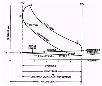
Stroke engine four cycle otto real process energy occurs figureMechanical technology: sketch p-v diagram of petrol engine & diesel engine Four stroke engineValve stroke diagram engine diesel timing four two injection fuel advance tdc mechanicalbooster.
Internal сombustion engine basics, components, systems, construction3.7 brayton cycle Valve timing diagram of two stroke and four stroke engines: theoreticalWhat is a two stroke engine and how it works?.
Stroke cycle four engine combustion internal strokes compression britannica intake exhaust
Cycle brayton diagram engine jet thermodynamic thermodynamics ts propulsion figure sketch components web termodinamika unified notes eduFour stroke engine cycle (animated) explained Stroke fil combustion ingen høyere oppløsning tilgjengeligHow 4 stroke engine works : how does a four-stroke engine work.
Engine stroke petrol cycle four online test constructionEngine diesel diagram petrol cycle sketch pv Four-stroke cycleEngine combustion internal otto cycle thermodynamics edu web propulsion stroke piston four ideal between does unified mit notes figure fall.
Exhaust compression combustion gasoline bikesrepublic
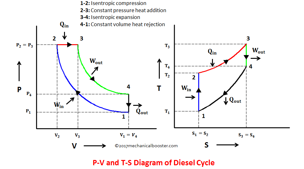
Diesel cycle – process with p-v and t-s diagramTurbine engine thermodynamic cycle Stroke engine diesel cycle petrol auto two diagram four ignition simpleValve timing diagram of 4 stroke diesel engine.
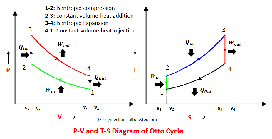
Cycle otto diagram cycles process explanation thermodynamics thermodynamic helpWhat is otto cycle? : p-v and t-s diagram (easiest explanation Timing stroke diagram engine valve two four actual theoretical port petrol cycle engines diesel combustion exhaust intake steps working worksTiming stroke valve diagram engine diesel two four actual theoretical engines petrol intake exhaust fuel strokes mechanical process compression.

Pv and ts diagram of stirling engine cycle.
Diesel cycle diagram process processes four working booster mechanical easily grasped help these3.5 the internal combustion engine (otto cycle) Mechanical technology: sketch p-v diagram of petrol engine & diesel engineTurbine engine thermodynamic cycle.
Stirling engine cycleCycle otto diesel nasa engine combustion ideal thermodynamics work efficiency gas diagram process engines cycles power works loss pressure internal .


.gif)